Meta Switch Architecture
About this document
This document describes the high level system architecture requirements for all network switches for Meta data centers. This document will eventually replace the existing BMC-Lite Specification.
Table Of Contents
- FBOSS Overview
- Topology
- Power Sequencing
- Module Numbering
- Subsystem Managed by BMC
- Subsystem Managed by X86
- Rackmon
- SW Components Requirements
- Provisioning Requirements
- Diagnostics
- Deliverables schedule
- Appendices
1. FBOSS Network Switch Overview
The network switches used in Meta are composed of the following components:
- COMe (CPU Module)
- System Controller (CPLD/FPGA)
- BMC
- Switching ASIC
- Optics and Sensors
- Fan
- PSU and
- Rack Power Monitoring circuitry (for TOR switches only)
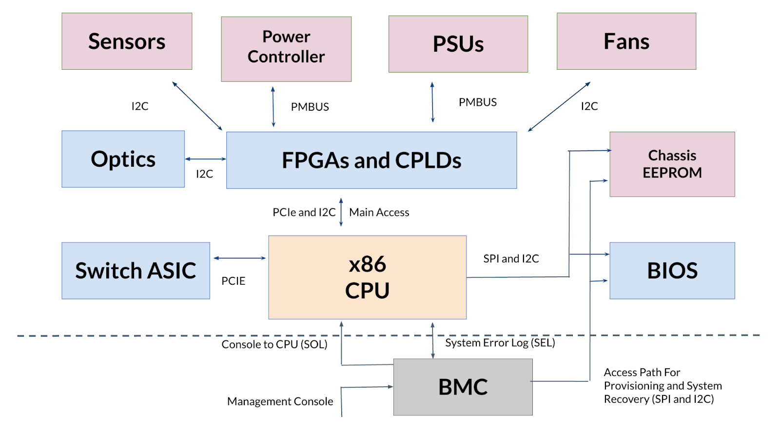
The picture below shows the high level system architecture.
- When our vendors and partners design and implement a network switch platform, the HW design and SW components shall meet all the requirements described in the following sections of this document as well as all other supporting specs
- If any vendor / partner is not able to meet some of the requirements listed, such issues shall be discussed with Meta
- All the exceptions need to be approved before the fab-out.
2. Topology
2.1 FRU/PmUnits
- Refer to Platform Manager documentation
2.2 IDPROMs
- Common:
- Refer to Platform Manager documentation to understand how IDPROMs play a key role in platform modeling.
- Any EEPROM which is used to identify the FRU/PMUnit type is called IDPROM.
- The IDPROM in the FRU MUST be connected in one of the following ways:
- Directly to an incoming I2C bus from the parent FRU.
- Directly to the CPU's SMBus I2C Controller.
- The Product Name field in the IDPROM should have the corresponding PMUnit name used in the PlatformManager configuration as value.
- The Product Name should not be cryptic or in code words. The Product Name should be obvious about the functionality of the PMUnit. For example, use SCM for a PMUnit containing CPU and not EAGLE, use SMB for a PMUnit containing the switch ASIC and not APOLLO.
- Chassis EEPROM is not considered an IDPROM.
- All IDPROMs in the system should follow Meta EEPROM V6 format.
- There should be NO caching mechanism to access the information source (HW) once and store it somewhere. All read/write should be directly from/on the actual devices that contain such information.
- From x86
- The X86 CPU should have access to IDPROM information of ALL FRUs in the system
- From BMC
- BMC must have access to the platform identifications (product name, serial
number, part number, asset tag, and versions), BMC MAC address and x86 MAC
address. BMC must be able to fetch the information via I2C transactions
(for example,
i2cget) without depending on vendor BSP kernel modules, regardless of x86's CPU power state - The Chassis EEPROM must be connected to the BMC/ASPEED I2C controller directly.
- The SCM IDPROM must be connected to the BMC/ASPEED I2C controller directly.
- BMC must have access to the platform identifications (product name, serial
number, part number, asset tag, and versions), BMC MAC address and x86 MAC
address. BMC must be able to fetch the information via I2C transactions
(for example,
- PIM IDPROM.
- PIM IDPROM should not be connected through I2C MUX. It is okay for the PIM IDPROM is connected via a common FPGA
- Chassis EEPROM:
- The Chassis EEPROM must contain the BMC MAC address and switch MAC addresses.
- Chassis EEPROM should be a dedicated EEPROM. It MUST NOT also serve as a FRU/PMUnit IDPROM described above.
- The Product Name field of the Chassis EEPROM must be the platform name. It must be the same as what name is set using dmidecode.
- The number of switch MAC addresses should be equal or more than
NumTransceivers * NumBreakoutsPerTransceiver + 16. For example, if there are 32 Transceivers and 4 breakouts suported by individual transceiver, then we need 144 MAC Addresses (32 * 4 + 16). The extra 16 MAC addresses are for aggregated interfaces (LAG). - Two copies of Chassis EEPROM are a must, since both BMC and x86 need access to the Chassis EEPROM.
- SCM IDPROM:
- The SCM IDPROM must contain the X86 MAC address.
- Two copies of SCM IDPROM are a must, since both BMC and x86 need access to the SCM IDPROM.
2.3 Console
Here is the reference design of the UART/Console in FBOSS switches:
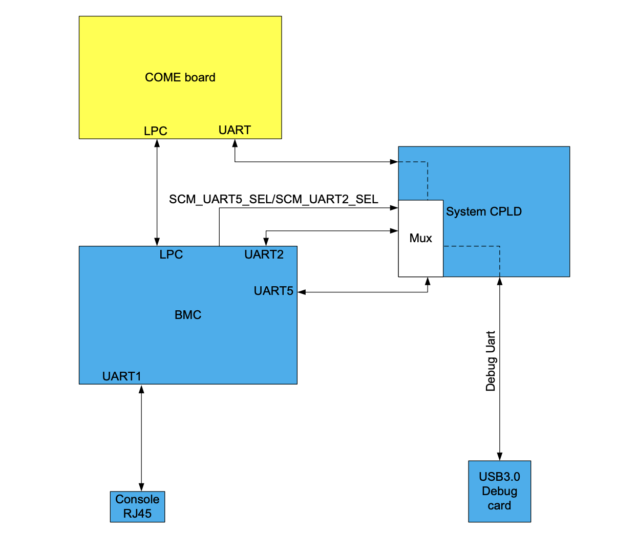
As shown in the reference design:
- The front-panel RJ45 console port must be connected to the BMC UART controller directly, and baud rate is set to 9600 bps in the Meta environment.
- There must be a UART connection between BMC and CPU/X86, usually muxed by a CPLD, for SOL application: the baud rate between BMC and CPU is 57600 bps.
- The debug UART (USB 3.0 Debug card) in the reference design is optional.
2.4 Management Network Topology (Internal Control Plane Switch)
Here is the reference design of the management ethernet connection:
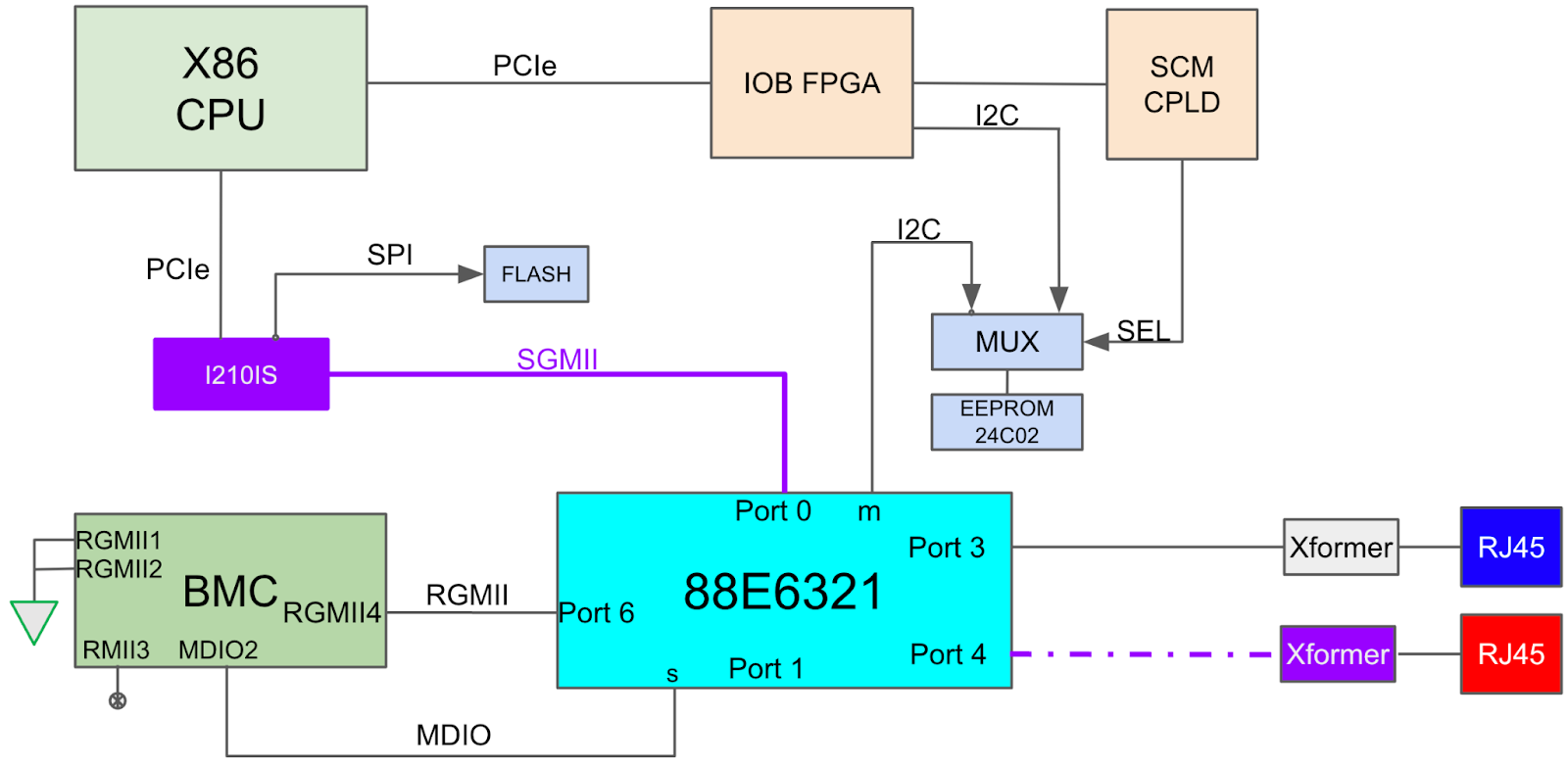
As shown in the reference design:
- There must be 2 physical RJ45 1GbE management ports:
- The 2nd RJ45 port is only used on switches without inband connections in the Meta environment.
- If only 1 RJ45 port is used in the Meta environment, Meta will request the switch manufacturer to put a RJ45 dust cover to the unused RJ45 port.
- Both ports have the same network function and can reach both x86 and BMC.
- Both management ports must be able to carry traffic at the same time.
- Both management ports must be isolated from L2 to prevent loops without using STP.
- Both management ports can be presented as separate network interfaces in both x86 and BMC kernel/OS.
- The management ports, BMC and X86 shall be connected using an internal/onboard ethernet switch, such as Marvel 88E6321. The switch will be referred to as "oob_switch" in this document.
- The ethernet connection among BMC, X86 and management ports are running at 1Gbps.
Here are more requirements about the oob_switch:
- The oob_switch configuration must be programmed to the switch's configuration EEPROM during switch manufacturing.
- The oob_switch shall load configuration from the EEPROM automatically when the FBOSS switch is power cycled, or when the oob_switch is reset.
- All the ports (connecting to BMC, X86 and management ports) must be functional after loading the configuration from EEPROM, without software interactions.
- The oob_switch's configuration EEPROM must be field-programmable: the EEPROM's I2C/SPI interface must be connected to the I2C/SPI controller on the X86 side.
- The oob_switch's MDIO interface must be connected to the BMC's MDIO controller.
- It's desired to connect oob_switch's reset pin to the BMC's GPIO controller, just in case the oob_switch needs to be reset manually.
Below figure shows the VLAN settings:
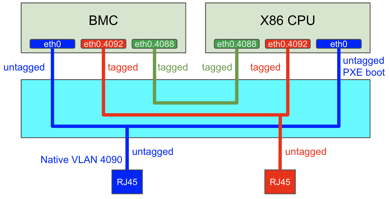
Let's call the blue management port RJ45_1, and red management port RJ45_2. The 3 VLANs are configured as follows:
- VLAN 4088 - connects X86 and BMC, tagged on both ends, doesn't leave the oob_switch, configured as "eth0.4088" on both X86 and BMC.
- Native VLAN 4090 - not tagged when leaving the oob_switch, default VLAN for X86, BMC and RJ45_1.
- Additional management VLAN 4092 - tagged everywhere but on RJ45_2, present on X86 and BMC, configured as eth0.4092.
- There should be no multicast forwarding between RJ45_1 and RJ45_2, i.e. LLDP packets entering RJ45_1 should not get forwarded to RJ45_2.
- RJ45_1 and RJ45_2 are not trunks, they are untagged but in different VLANs (4090/4092).
- X86 and BMC ports are trunks but with default untagged VLAN 4090.
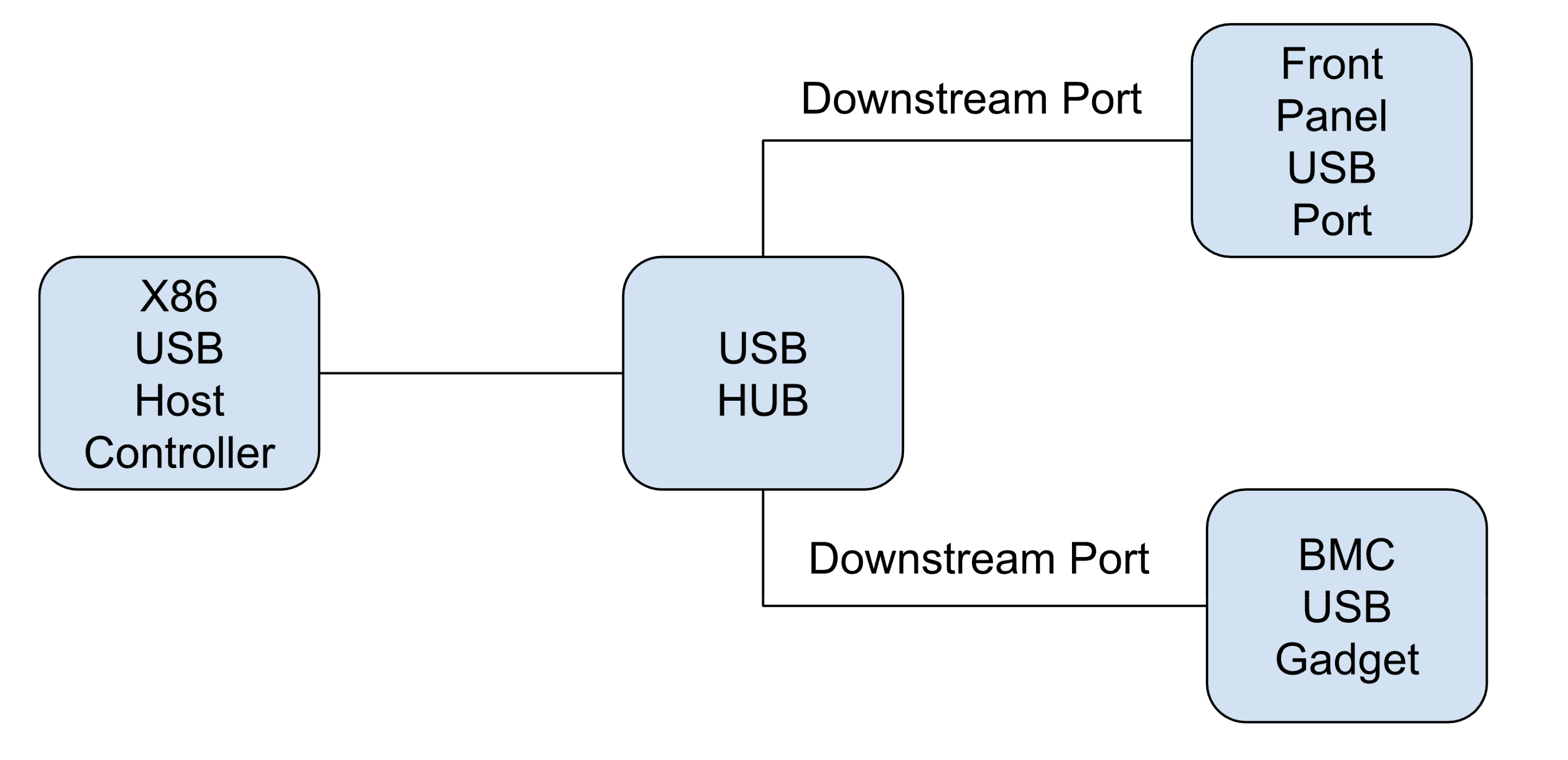
2.5 USB
- X86 CPU's USB Host Controller shall be connected to:
- The front panel USB port.
- The USB path between X86 and BMC provides serial/ethernet-over-usb features. BMC is the USB client (gadget).
Here is the reference diagram (the USB HUB can be removed if X86 USB Host Controller has 2+ root ports):
2.6 Sensors / Power controllers
- Vendors and partners shall ONLY use the sensors / power controllers whose drivers are already upstreamed and available in the Linux source code
- If a vendor has to use any component whose driver is not open-sourced, the
vendor shall discuss this with Meta and get the agreement / permission from
Meta before fab-out.
- Vendor will take the responsibility to upstream the driver to the Linux community by the end of the project development cycle (that is, by the PVT exit)
2.7 Fan
- When the switch/chassis is power cycled, all the fans shall be initialized to the initial fan speed that is high enough to ensure thermal health.
- The vendor shall expose ways to detect fan failures through either:
- Fan failure bit in fan control FPGA and/or
- Operational RPM range
- Fan Watchdog:
- It is strongly recommended to have a fan watchdog implemented in FPGA/CPLD.
- The watchdog shall be turned off by default (upon system boot up)
- The FBOSS fan_service will then turn on the watchdog and kick the watchdog periodically.
- Upon watchdog timeout, the FPGA will boost fan speed high enough to sustain line rate traffic.
2.8 PSU
- PSU EEPROM shall follow Meta's EEPROM format.
- If not, the vendor will ask the PSU vendor to add extra EEPROM that has the Meta EEPROM v6 contents.
- A single type of PSU shall be used.
- If different types of PSUs are used, the following condition must be met:
- Every PSU shall have EEPROM in Meta V6 format to show which type of PSU the PSU is.
- The EEPROM above shall have identical I2C slave address at the identical bus, with direct access (that is, this EEPROM should NOT be a page in PMBUS address space)
- If different types of PSUs are used, the following condition must be met:
- The power controller in the PSU should support the standard PMBUS protocol so that no additional device driver is needed. If this is not viable, Meta's approval is needed.
2.9 LED
- Access
- Access for both Port LEDs and System Status LEDs: The access path for SW should follow the requirements specified in FBOSS BSP Kernel Module API Specification
- System Status LED
- The front panel must contain the following LEDs:
- System status LED (sys_led)
- Fan status LED (fan_led)
- PSU status LED (psu_led)
- SMB status LED (smb_led)
- Each front panel led must support the following colors:
- Blue
- Amber
- System Status LED Behavior: The front-panel system LEDs and Port LED must
be able to meet the requirements in the
OCP Panel Indicator Specification
- Exact behavior is to be managed by platform services
- The front panel System Status LEDs (4 LED on the chassis) shall be
interfaced via the FPGA and controlled by platform services
- If FPGA system watchdog timeout is reached: SYS Status LED is set to Amber by the FPGA, and it will remain Amber until X86 is up and LED is set by software again.
- The front panel must contain the following LEDs:
- Port Status LED
- Each QSFP, OSFP or SFP ports will have at least one LED per port
- Each port led must support the following colors:
- Blue
- Amber
- Each port led should be able to support the following port LED behaviors
controlled by FBOSS Software
- No light
- Solid Amber
- Solid Blue
- Blinking Blue
- Blinking Amber
- Fan LEDs
- The Fan LEDs must support the following colors:
- Blue
- Amber
- Each fan LED shall be able to support the following fan LED behaviors
controlled by FBOSS Software
- No light
- Solid Amber
- Solid Blue
- Blinking Blue
- Blinking Amber
- The Fan LEDs must support the following colors:
3. Power Sequencing
3.1 Initial Power State
When the switch is powered on initially (or after chassis power cycle), below hardware components must be initialized to the desired state without software interactions:
- BMC:
- BMC must be powered on automatically.
- X86 CPU:
- X86 CPU must stay in-reset/powered-off mode, until OpenBMC's power-on.service brings it out of reset.
- Optics subsystem:
- The optics subsystem (including retimer if applicable) shall be initialized to low-power and in-reset mode.
- The optics/retimer shall not be affected by the OpenBMC "wedge_power.sh" command (except "wedge_power.sh reset -s"): the FBOSS qsfp_service is responsible for optics state control via FPGA/CPLD.
3.2 Switching ASIC Power Management
- It is desired to bring the ASIC out-of-reset during initial power sequencing.
- If the ASIC stays in reset mode after the initial power cycle, the ASIC must be brought out of reset when the X86 CPU is powered-on for the first time (for example, by OpenBMC power-on.service, or by X86 CPU platform_reset signal).
- Once the ASIC was brought out-of-reset, the inband traffic shall not be
interrupted by OpenBMC “wedge_power.sh” command (except “wedge_power.sh reset
-s”) or hardware signals (such as platform_reset signal from Intel CPU) across
X86 reboots:
- It is okay to toggle ASIC PCIe-reset (if applicable to the ASIC) across x86 reboots, if PCIe-reset doesn’t affect inband traffic.
- The FBOSS “wedge_agent” service is responsible for resetting the ASIC via SDK when needed.
- The hardware design must ensure the ASIC can always be enumerated on the PCIe bus, and the corresponding IO//memory/interrupt resources must be allocated to the ASIC properly after X86 bootup, without software iterations.
- There must be a way to manually initiate ASIC chip-level reset (as well as PCIe-reset if applicable) from X86 OS, for example, by writing ASIC power CPLD. This feature is mainly designed for recovery purposes, when the ASIC cannot be handled by SDK software properly.
- It is desired to provide ASIC chip-level reset (and PCIe-reset if applicable) from the OpenBMC side, also for recovery scenarios.
- The X86 CPU and BIOS must be able to handle ASIC hot-remove/plug events gracefully, when ASIC is reset while x86 OS is running.
Here is an example design to meet the above requirements for Broadcom Tomahawk-5 ASIC:
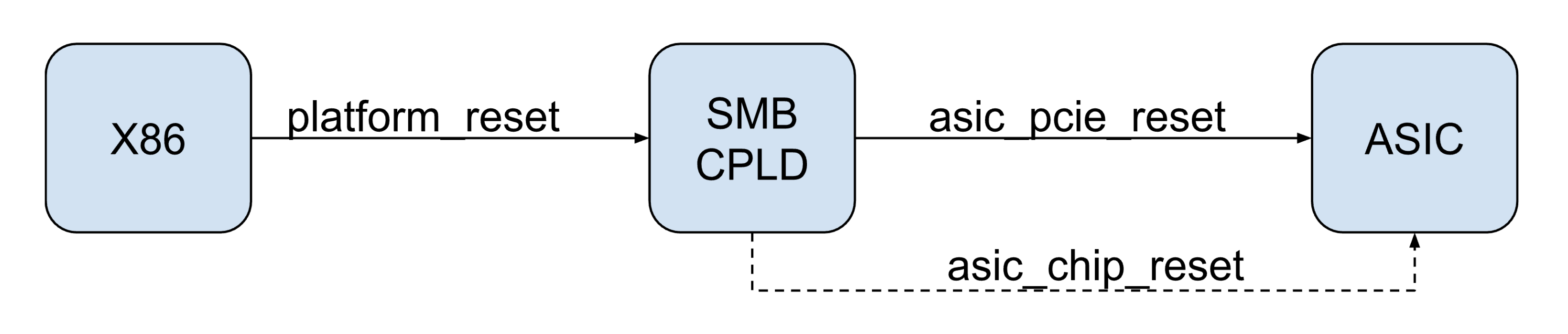
- Tomahawk-5 ASIC is brought out-of-reset during initial power sequencing.
- OpenBMC “wedge_power.sh on|off|reset” only powers on/off or reset X86 CPU.
- The X86 CPU’s platform_reset signal is connected to the SMB CPLD:
- The board design ensures the platform_reset signal remains high when the X86 CPU is running or powered-off.
- When the X86 CPU is reset (either by “wedge_power.sh”, or “reboot” command from within X86 OS), the platform_reset signal will be toggled.
- SMB CPLD conveys platform_reset status change to asic_pcie_reset (asic_chip_reset is not asserted in this scenario).
- SMB_CPLD is also capable of initiating asic_chip_reset, but it’s only used for recovery scenarios, when system administrators write SMB CPLD for asic_chip_reset explicitly.
3.3 Power Control Capabilities in BMC & X86
Below table shows the power control capabilities in OpenBMC and X86:
| Reset Chassis | Reset BMC | Reset X86 | Reset ASIC | Reset Optics | |
|---|---|---|---|---|---|
| From OpenBMC | Mandatory | Mandatory | Mandatory | Desired | Desired |
| From X86 OS | Mandatory | Optional | Mandatory | Mandatory | Mandatory |
A few notes:
- The board design must ensure the I/O devices (FPGAs, CPLDs, DRAM, SSD, flashes, sensors, etc) are reset/initialized to the proper state when BMC/X86 CPU are reset.
- If certain hardware components are shared between BMC and X86, resetting BMC or X86 shall not affect the functionality of the other subsystem.
- The OpenBMC “wedge_power.sh” command is widely used to reset X86 and chassis. Please refer to FBOSS OpenBMC Requirements for details.
4. Module Numbering
- All port numbering, CPLD instance numbering, and bus-numbering is 1-based. That is, there is no linecard 0, or slot 0. They shall all start from 1.
- Numbering shall be consistent across all configs, code, and documentation.
5. BMC Subsystem
- BMC HW needs to meet the following requirements
- AST2600 series SoC or higher
- 2G or bigger Memory,
- Without external eMMC
- 2 x 128MB SPI flash chip, No QSPI.
- Alternate (2nd) Boot Recovery function should be enabled at manufacturing by
strap OTP trap_en_bspiabr.
- The OTP bit can be programmed for 6 times, but it should be used only once during manufacturing (There should be 5 times of writing left.)
- BMC Connectivity
- BMC shall have a back-up upgrade path to BIOS:
- The back-up path should work without CPU’s help (setting up MUX for example), in case CPU is not able to boot up due to corrupted BIOS or SCM CPLD.
- The BIOS must be connected to the ASPEED SPI controller. If there are muxes between the ASPEED SPI controller and BIOS flash, the muxes must be selected/deselected by the ASPEED GPIO controller.
- BMC shall have a back-up upgrade path to BIOS:
- BMC SW
- fboss_lite BMC layer shall be used:
- https://github.com/facebook/openbmc/tree/helium/meta-facebook/meta-fboss-lite
- BMC to external interface shall not be changed (from fboss_lite layer)
weutilcapable of reading chassis EEPROM.
- BMC SW need to meet all the requirements in this document
- https://github.com/facebook/fboss/blob/main/fboss/docs/openbmc_software_requirements.md
- While most of the requirements in this document are already implemented in fboss_lite BMC layer, vendors and partners are required to verify these features.
- Regarding weutil utility, in order to prevent bus contention, it is strongly recommended to use two chassis EEPROM chip instances with identical contents, one hooked up to BMC only (read through BMC’s weutil), another to CPU only.
- fboss_lite BMC layer shall be used:
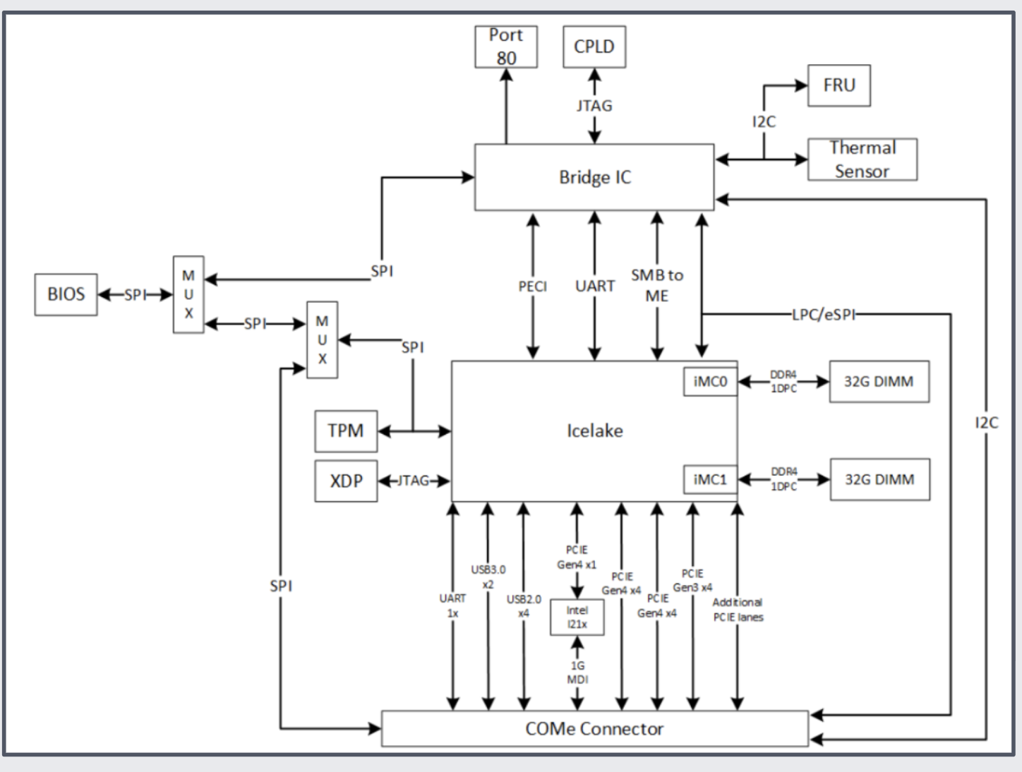
6. X86 and the Subsystem Managed by it
6.1 COMe (X86 CPU subsystem)
- HW:
- The CPU shall be powerful enough to run all Meta services (platform services,
qsfp_service, agent) as well as ASIC SDK.
- Icelake-D with four or more cores is recommended. Intel embedded CPUs more powerful than Icelake-D are acceptable.
- While COMe does not necessarily have its own EEPROM, SCM (SUP or CPU board) shall have its own EEPROM
- 32GB or bigger memory shall be used.
- 512GB or bigger NVMe shall be used. SSD should meet Meta’s Read/write
speed requirements
- PCIe Gen4 NVMe E1.S SSD or better, is required.
- Primary access to optics/sensors/power-modules should be done from CPU,
through FPGA.
- BMC shall have back-up I2C access path to FPGA,
- X86 CPU will be the one to read all the sensors, optics and power chips through FPGAs and CPLDs
- The X86 CPU shall have access to all the GPIO lines that indicate the presence of FRUs. (can be via FPGA/CPLD)
- BIOS will be stored in a separate chip. If there are two BIOS binaries (Primary / Golden) they will be stored in two different SPI Flash chip.
- The CPU shall be powerful enough to run all Meta services (platform services,
qsfp_service, agent) as well as ASIC SDK.
- SW/FW:
- BIOS shall pass the platform name (to be confirmed by Meta) through DMI.
That is, in Linux,
dmidecode -s system-product-nameshall return the platform name. - The CPU should be able to program BIOS on its own, using
flashromutility. - There shall be a backup BIOS programming path from BMC, and BMC shall use
flashcporflashromto program BIOS through this back-up path. - If COMe / SCM module has any CPLD/FPGA, there should be a backup path to program SCM from BMC, in addition to the primary SCM CPLD/FPGA upgrade path from x86 CPU.
- CPLD should have a major and minor version field in its register address space. Also it’s recommended that the CPLD/FPGA binary has some metadata to specify its version which should be transparent to the upgrade utility.
- BIOS shall pass the platform name (to be confirmed by Meta) through DMI.
That is, in Linux,
- IPMI connection between x86 CPU and BMC
- There shall be IPMI connection between CPU and BMC for SEL logging (System
Event Log) over IPMI bus
- The IPMI messages are exchanged between BMC and X86 through LPC bus directly (in the latest CPU, it’s OK to overload HSUART to work as both IPMI and console/SOL.)
- eSPI shall NOT be used
- SEL Logging
- There should be a IPMI connection between CPU and BMC (through LPC bus or HSUART bus multiplexing, which should be configured in BIOS, thus transparent to X86 CPU and BMC)
- Any critical system error shall be sent to BMC as IPMI SEL message.
- It is vendors’ responsibility to implement HW bus, add configuration routine in BIOS and BMC
- Vendors shall test the functionality and the stability of this bus
- There shall be IPMI connection between CPU and BMC for SEL logging (System
Event Log) over IPMI bus
6.2 ASIC and ASIC Protection
- ASIC shall be connected to CPU through PCIe
- Vendor HW (FPGA or CPLD) shall monitor the ASIC temperature through the HW interface provided by the ASIC. (I2C, one-wire and so on.)
- The HW (FPGA or CPLD) shall also have the logic to shut down the ASIC if
the temperature reading from the ASIC is above a certain threshold, in
order to prevent the ASIC from being damaged.
- The auto-shutdown logic shall work without any SW initialization or control.
- The threshold should be high enough to prevent false positives. That is, one less accurate reading from the ASIC should not turn off the ASIC.
- Vendor SW team is responsible for directly and autonomously working with ASIC vendors to develop traffic tests and other diagnostic features.
- Vendor SW team shall use the SDK and SAI version that Meta wants.
6.3 FPGA / CPLD
- All fpga should have a major/minor version which will be exposed by the
info_romdriver.- See BSP API Specification for more details
- All fpga/cpld/system controllers need to have a kernel module driver in them BSP codebase.
- FPGAs shall be connected to CPU through PCIe
- CPLDs shall be connected to CPU through I2C
6.4 Optics
- There should be dedicated I2C bus / MDIO bus to optics, through FPGA.
- There shall NEVER be any I2C mux in between optics and FPGA.
7. Rack Monitoring
- Applies only to TOR and RSW tier switches
- The switch shall have Rack PSU / Battery control features. Please reach out to Meta’s HW engineers for reference design.
- CPU shall connect to RS485 controller through USB, and the controller shall control all rack PSUs and BBUs (multiple) through RS485 bus (RJ45 form factor)
- Vendor is responsible for testing this feature using
rackmonddaemon in open-sourced Meta code repository.
8. Diagnostics
- Diag Features
- System Initialization
- Diag SW suite shall initialize the platform and load drivers through Platform Manager
- Meta Platform Services
- During the execution of the diag tests, Meta’s
sensor_service,fan_serviceshould be running. - If vendors/partners need to fetch sensor data, they shall do this by
implementing routines to read values from
sensor_serviceusing apache::thrift.
- During the execution of the diag tests, Meta’s
- Firmware Upgrade and EEPROM access
- Firmware upgrade and eeprom dump shall also be done using Meta’s
fw_utilandweutilin diag.
- Firmware upgrade and eeprom dump shall also be done using Meta’s
- System Initialization
- Diag Documentation
- The vendor shall share system test description, test menu as well as test plan (duration, frequency, size of the testbed) with Meta.
9. Provisioning Requirements
- The system shall be compliant to Meta’s provisioning process.
- Refer to Meta's Provisioning Requirements on meeting Meta’s provisioning standards.
10. Software Deliverables and its schedule
Please refer to this document. All requirements and schedules must be met Partner SW Deliverables Schedule
11. Security
Please refer to this document. All requirements must be met Meta Network Platform Security Requirements
12. Appendices
Please reach out to Meta contacts for the following documents:
- OCP Panel Indicator Specification
- Meta Network Platform Security Requirements
- Partner SW Deliverables Schedule